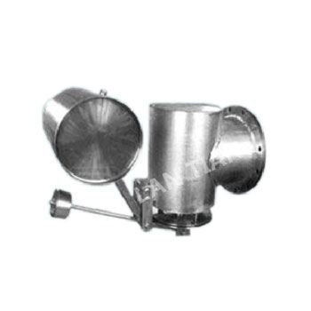
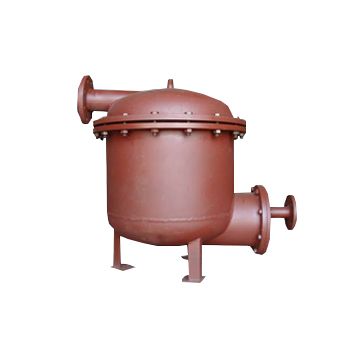
Dehydrator LTQS type
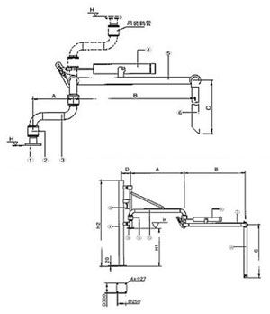
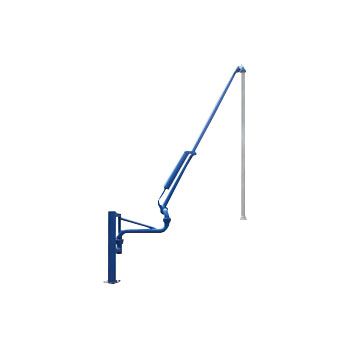
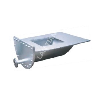
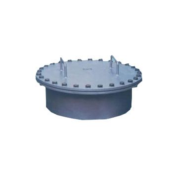
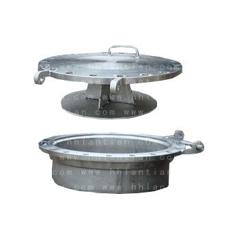
Functional useFunction: it is installed on the dewatering pipe or blowdown pipe at the lower part of the oil storage tank to automatically open and close the drainage after drainageApplication: it is suitable for automatic oil interception and drainage of oil tanks in oil and petrochemical industriesWorking principleThis product is composed of cylinder, inlet and outlet valves and automatic control device (see Figure 1). The buoyancy is generated by the density difference between different oil media and water, and the lever principle is adopted to make the buoy move up and down by relying on the buoyancy difference of the buoy in the oil-water medium. The obtained buoyancy difference is magnified by the high-sensitivity lever system to control the opening and closing of the drain valve, so as to achieve automatic operation. At the same time, the product adopts the special design structure without back pressure to make the opening and closing of the valve more sensitive. It can also realize the automatic monitoring of the system according to the needs of users and automate the dehydration management in the tank farmThe upper part of the dehydrator shell is provided with a water inlet, the lower part is provided with a water outlet, a floating ball is connected with the small valve core at the other end through the connecting rod, and the counterweight is installed on the upper part of the floating ball through the connecting rod. When the floating ball rises or falls under the action of buoyancy, the valve core is driven to open or close the drain through the connecting rodCharacteristics1. The dehydration principle breaks through the traditional concept of automatic water cutting of oil tank. It perfectly uses Archimedes theorem and lever principle, and realizes automatic dehydration without power supply according to the relationship between oil and water density difference, which is intrinsically safe and reliable2. It skillfully solves the problem that the residual oil in the dehydrator cannot automatically return to the oil tank in the dehydration process3. At the end of each dehydration, the water level in the dehydrator is always maintained at a certain height to form an automatic water seal to ensure no oil spillage 4. Complete functions and wide application range5. There are no wearing parts, long service life and convenient installation and maintenance. There is no need for tank cleaning and hot work during installationTechnical parameters1. Working pressure: & le; 0.6Mpa2. Operating temperature: & le; 80 ℃ (steam tracing control as required) 3. Nominal water cut: below 10t / h, 12t / h, 15t / h, 20t / h, 30t / h4. Cut water oil content ≤ 100mg/L5. Scope of application: suitable for liquid separation of oil products and other chemical products with different specific gravityModel descriptionModel descriptionProduct structure size Model H(mm) L(mm) Water cut T / h Inlet pipe diameter Outlet pipe diameter Cylinder diameter (mm) Applicable media LTQS-10 660 724& le; 10 DN80 DN50 Ф 500 For light oil or liquid chemical raw materials LTQS-12 680 724 12 DN80 DN50 Ф 500 Ibid. LTQS-15 700 724 15 DN80 DN50 Ф 500 Ibid. LTQS-15A 700 824 15 DN80 DN50 Ф 600 For light oil, liquid chemical raw materials or crude oil LTQS-20A 720 824 20 DN100 DN50 Ф 600 For crude oil, residue and wax oil LTQS-30A 720 824 30 DN100 DN50 Ф 600 Ibid. Installation diagram1. This product is required to be installed on a stable and solid foundation. The water inlet shall be flat or slightly lower than the oil tank drain2. There are two installation methods: ① installation of oil tank without siphon (see Figure 2). ② Installation of oil tank with siphon (see Figure 3)3. All fasteners in the pipeline shall be tightened, and the connection point shall be sealed, and liquid leakage is not allowed. The water cut-off shall be debugged and fixed by matching the counterweight code of corresponding model according to the oil type of the user4. The valves connecting the oil tank and the dehydrator shall be straight through valves such as gate valves and straight pipes without elbows, otherwise the oil return will be affected5. Steam heat tracing pipe shall be installed in northern areas to prevent freezing. The connecting valve between the dehydrator with steam heat tracing pipe and the oil tank shall not be closed to prevent overtemperature and pressurization Precautions 1. The valve at the outlet of the oil tank shall be of straight through type (such as single valve, ball valve, etc.)2. The pipeline from the oil tank to the dehydrator shall be horizontal or slope to the dehydrator3. The oil tank outlet pipe is equipped with elbow (siphon type). It is recommended to cancel the elbow. If the elbow cannot be cancelled, an oil return pipe must be set, with a diameter of DN324. & ldquo; should be set for the dehydration of Dacron in cold areas or viscous oil products; Self supporting temperature control valve & rdquo5. It is recommended to add heat tracing and insulation to the dehydration pipeline and oil return line of oil tank in cold areas6. For oil tanks with large volume or oil products with high moisture content or short dehydration cycle, it is recommended to appropriately increase the number of dehydrators7. Regularly remove the sediment in the dehydrator and filter to ensure the normal operation of the dehydrator8. Regularly check whether the dehydrator leaks oil, and timely replace the sealing ring of the double valve9. Pay attention to exhaust during the operation of the dehydrator to avoid gas resistance affecting the normal operation of the dehydrator10. It is normal that the dehydrator cannot dehydrate normally in case of emulsified oil sludge layer, and a manual water cut-off shall be set in front of the dehydrator